

Technical Q&A
Make a selection below or use the search to find an answer to commonly asked questions.
Accessories (3)
The Zzero circuit is relatively simple.
First, any time you run the ZZero, take a second to test it.
Touch the Z zero clip directly to the plate. While it is touching input 1 should come on in the Inputs section of the Red Position Window. Here is a picture showing the Input #1 triggered in the Red Position Window.

If it doesn’t come on then something in the ZZero circuit has an issue, such as a wire having come loose or disconnected.
For current versions of the ZZero assembly there will be a plug on the ends of the black coil cables that comes off of the alligator clip and aluminum plate. This connector is designed to be plugged in only one way, but it is possible to plug it in upside down if it is really pushed in there. Here is a picture that shows what the wiring should look like going into both halves of the connection.

Here are the pertinent ZZero connections to check:
Ground clip – The ground clip needs to wire to GND on the main control board – there generally is a green wire for this.
Zero Plate – The plate needs to wire to input 1(1/ZZ) on the main control board – there generally is a black wire for this.
If it does come on then simply clip the clip on the collet nut or bit, then test it by touching the plate to the bit, input 1 should come on. Now run the ZZero routine.
The bit comes down but stops on the plate during the ZZero routine.
If your Input #1 is triggering when the clip touches the plate, and when the bit touches the plate during the ZZero routine, but the bit just stops then a setting in your software may need to be changed.
Go to Values>Cutter Values and check to make sure that your Safe Z Pull Up Value is set to something greater than 0. Most ShopBot users set this to 1, unless you do not have a lot of clearance over your material in which case 0.2 can be used instead. Here is a picture of the setting to change.

Here are a couple of documents we have on operating and maintaining the pump. Click on the link to open the corresponding document in a new tab.
If you cannot find the information that you are seeking in this documentation, then it may be worth reaching out to Becker with further questions or for replacement parts. ShopBot Tools Technical Support may also be able to answer your questions and can be reached at Support@ShopBotTools.com
Here is the Website and Contact information for Becker. They are usually very responsive.

A zip file with the files can be downloaded here:
Here is the Instruction Manual as well, just in case it is needed.
Accessories:Bits (1)
Feeds and Speeds
Here is the best info we have here in support. This is one of the hardest things for people to get right as it is a learned skill to come up with and adjust feeds/speeds. There is no set in stone number for any project:
The info I am providing is on feeds/speeds and calculating them using chipload. I am including some document links and want to throw in a couple of reminders that chip-load values are key, so finding you bits chipload from the manufacturer and then finding the federate plus 12k-18k rpm that gets you the chipload:
A good place to start –http://www.woodguide.org/files/2014/…bit_basics.pdf
A good reminder to use chipload calculations –http://www.talkshopbot.com/forum/sho…-find-the-data
And an extra reminder that chiploads are based on a 1x full depth cut. 1x full depth is the diameter of the bit. So a ¼” bit has a 1x full depth of cut of ¼”.
ShopBot Tutorials
See feeds and speeds category
Feeds/Speeds (videos)
Tips for Cutting Aluminum
Cutting Acrylic
Tool Database and Bit Selection
Plywood
Plastics
For milling (but the techniques are very similar)
Documents (PDF’s)
Selecting the Right Bit/Feeds and Speeds Charts
Feeds & Speeds Quick Reference
Feeds & Speeds Plastics
Tips for Cutting Aluminum
Control Computer (1)
We highly recommend our pre-setup control computers for running on USB-USB enabled ShopBots to avoid common setup and Windows based issues.
PC Setup
The PC setup can be daunting to many users, and you may need an IT professional to help you, but to succeed with the ShopBot and have it work as smoothly as possible, the control computer must be set up accordingly.
If you are in an educational setting you need your IT dept to provide you a standalone workstation that is not managed by group policy or on the network.
For all applications, the PC must be a clean installed standalone workstation. This will wipe/delete all data/files/programs from the computer.
For the workstation setup a clean install is needed, below is our best information on how:
https://www.youtube.com/playlist?list=PLf632tVju0dEzZ5LnKpb98aaY2HkQMJtj
— Computer Requirements – https://youtu.be/HgsEVSRpJqM
Installing Windows with USB Installer – https://youtu.be/eGQc6uvak3Y
Installing Windows with CD – https://youtu.be/BcGihWMHefk
Setting up Control Computer – https://youtu.be/WEVWW93DvbA
Installing the Control and Design Software – https://youtu.be/-Pb5YzfZcUY
1.) Make sure we are not using a port that is 3.0 if earlier than Windows 10. This is usually a blue colored port or labeled with an SS icon or will just say 3.0 or USB 3.0. We do not want to use this. It is not going to be compatible with the controller. USB 3.0 is fine for windows 10
2.) Make sure the usb cable is not over 10ft or extended in any way.
3.) Make sure the usb port is connected directly in the computer and not a hub.
Desktops (DT24x18) (2)
Maintenance on a Desktop generally includes cleaning up (vacuuming or blowing debris from the machine) after cuts are done. The motor drive screws are Teflon coated – DO NOT lubricate them, as the lubricant will cause the machine to not run properly and will damage the Teflon.
Motor Screws – Wipe screws with a clean dry cloth.
DO NOT USE any kind of lube or solvent-based cleaner on the Teflon coated screws. Doing so could cause the Teflon to flake off.
Rails – Wipe them with a clean, dry rag,
Apply a light coat of a machine oil. Wipe off excess oil as too much will attract dust.
After every 40 hours of use – Check for loose screws and parts.
On an as needed basis – Remove the clear plastic enclosure from the back of the machine and gently blow out any dust that has accumulated in the control area. This is especially true if cutting aluminum.
Prior to inserting a new bit – Wipe clean collets, collet nuts and collet end of arbor. Apply a light coat of machine oil with an oil damped rag (not soaked or dripping).
This router can be natively replaced with the Dewalt 2 1/4 HP (DW618) model.
Electrical Requirements (4)
Tools must be hard-wired to their own disconnect boxes by a licensed electrician.
Only Desktops, Desktop MAXs, and Handibots come with plugs. ShopBot does not supply a cable for hard-wiring. The electrician must select the appropriate cable.
We highly recommend our pre-setup control computers for running on USB-USB enabled ShopBots to avoid common setup and Windows based issues.
PC Setup
The PC setup can be daunting to many users, and you may need an IT professional to help you, but to succeed with the ShopBot and have it work as smoothly as possible, the control computer must be set up accordingly.
If you are in an educational setting you need your IT dept to provide you a standalone workstation that is not managed by group policy or on the network.
For all applications, the PC must be a clean installed standalone workstation. This will wipe/delete all data/files/programs from the computer.
For the workstation setup a clean install is needed, below is our best information on how:
https://www.youtube.com/playlist?list=PLf632tVju0dEzZ5LnKpb98aaY2HkQMJtj
— Computer Requirements – https://youtu.be/HgsEVSRpJqM
Installing Windows with USB Installer – https://youtu.be/eGQc6uvak3Y
Installing Windows with CD – https://youtu.be/BcGihWMHefk
Setting up Control Computer – https://youtu.be/WEVWW93DvbA
Installing the Control and Design Software – https://youtu.be/-Pb5YzfZcUY
1.) Make sure we are not using a port that is 3.0 if earlier than Windows 10. This is usually a blue colored port or labeled with an SS icon or will just say 3.0 or USB 3.0. We do not want to use this. It is not going to be compatible with the controller. USB 3.0 is fine for windows 10
2.) Make sure the usb cable is not over 10ft or extended in any way.
3.) Make sure the usb port is connected directly in the computer and not a hub.
Power Requirements are different for every tool. See ShopBot Docs- Electrical Requirements and find appropriate tool.
https://www.shopbottools.com/support/documentation/electrical
Check “Recommended Branch Protection” for Amperage requirements. If both a 110V and 220V line are required, then they each need to be hard wired with their own disconnect.
All electrical requirement documents can be found here: https://shopbottools.com/support-resources/electrical-requirements/
Control box setups – refer to appropriate install and mounting document depending on age of your tool.
Control Box Setup (Standard models)
Control Box Setup (Alpha models)
Overview of Power Supply and Placement for ShopBot (US and Canada) – download document
Overview of Power Supply and Placement for ShopBot (International)
– download document
International Customers (2)
The language of the computer’s operating system must be set to English, US. (If the computer user has admin privileges, then the language can be set to English for just the user).
Set the default language of the keyboard to the English language. (In some cases, it might be worth it to purchase an English keyboard.)
To avoid converting the computer entirely, create a new log In with administrative rights, and set that log In to English, US.
Mechanical Assembly (1)
Black goes to Input 1, green/blue goes to Ground, and red/brown goes to any of the +5 terminals (only needed for an accessory like a probe). These can be hooked to the terminal blocks by loosening the screw with a small flat head screwdriver, inserting the stripped wire end, and tightening the screw back down. Make sure there is a good connection to the wire (don?t insert the wire far enough for the screw to clamp down on the plastic insulation).
Standard Wiring Diagram (Different for Desktop and Alpha):

Post-Installation Problems (9)
Type VU into the ShopBot Console (the blank box next to the ShopBot CNC logo) or go into the Values menu in your Command Console and select Unit Values.

Find the axis you would like to reverse to movement of and add a negative sign (-) in front of the number next to that axis in the Value table.
The example below has the X axis with a positive value, and the Y axis changed to a negative value:

Do not change the absolute value of the number as that will affect the movement of your tool.
Symptoms: “My tool keeps losing connection” – Two types
1) Stuttering in the smooth motion of the tool, which results from the information stream being choked.
2) Connection losses, which results from the communication stream being distorted or fully blocked.
Most Common Problem: Computer Interference:
PC Setup
The PC setup can be daunting to many users, and you may need an IT professional to help you, but to succeed with the ShopBot and have it work as smoothly as possible, the control computer must be set up accordingly.
If you are in an educational setting you need your IT dept to provide you a standalone workstation that is not managed by group policy or on the network.
For all applications, the PC must be a clean installed standalone workstation. This will wipe/delete all data/files/programs from the computer.
For the workstation setup a clean install is needed, below is our best information on how:
https://www.youtube.com/playlist?list=PLf632tVju0dEzZ5LnKpb98aaY2HkQMJtj
— Computer Requirements – https://youtu.be/HgsEVSRpJqM
Installing Windows with USB Installer – https://youtu.be/eGQc6uvak3Y
Installing Windows with CD – https://youtu.be/BcGihWMHefk
Setting up Control Computer – https://youtu.be/WEVWW93DvbA
Installing the Control and Design Software – https://youtu.be/-Pb5YzfZcUY
1.) Make sure we are not using a port that is 3.0 if earlier than Windows 10. This is usually a blue colored port or labeled with an SS icon or will just say 3.0 or USB 3.0. We do not want to use this. It is not going to be compatible with the controller. USB 3.0 is fine for windows 10
2.) Make sure the usb cable is not over 10ft or extended in any way.
3.) Make sure the usb port is connected directly in the computer and not a hub.
Electrical Interference
Ground tool – usually grounding dust collection system is sufficient. Otherwise, may want to ground table bed (PRT tools only).
GROUNDING DUST COLLECTION
Links on Dust Collection Grounding
http://www.camheads.org/showthread.php?t=3800
Ideally, use a hose that has copper core wire.
Otherwise, coil a wire up into the hose (this is not ideal).
Connect the copper wire to a large metal object or building ground (preferable) at the dust bag end.
Also make sure the metal body of the dust collector is grounded.
DO NOT have any metal connection running between dust collection and tool – this will cause static to be discharged to the tool rather than away from it.
Other Solutions
Load Firmware.
Check Com Speed.
Check if tool is looking at the wrong port.
Check if the driver is actually loaded.
Check if the excess motor cables are looped up inside the control box.
Check to see if the low voltage sensor cables bundled with the motor cables/power cables.
Check if USB-Serial adapter is dead.
Checking Communication Speed
Depending on the version of the software, perform a baseline test on the communication speeds for the tool. If the version is unknown, check the ShopBot software’s Command Console under Help->About.
This only tests the USB/Serial connection, it does not test the PC in any way.
For 3.8.x versions, perform a move command over a distance of 12 inches. Do this through the command console and not the Keypad by typing a command like: MX, 20 (Move->X axis, 20 inches).
After the move command completes, go to Utilities->Diagnostic Information. The last value on the bottom right of that list should be a value called Packet_et. This is a rough check on how long a command takes to communicate with the controller. This should result in a value of ~35 or less.
For 3.6.x and lower, there should be a program in the C:\Program Files (x86)\ShopBot\Diagnostics folder called USB Speed Test. Perform the test and the tester will display a percentage. The percentage should be 75 or greater.
If these tests result in a poor communication speed, replace the cable connecting the PC to the tool.
See Troubleshooting Mechanicals guide on the website.
Making sure the right tool settings are loaded and recent firmware is loaded can prevent a variety of problems and often this will fix issues without doing any sort of diagnostics.
Open the ShopBot control software and type a UR command (or click on Utilities > Reset Default Settings values on the top menu bar). When asked to clear the system log, click Yes. Click Yes and OK to the next two boxes that pop up. A window should pop up asking to select a settings file for the tool. Click on the profile that matches the tool (PRS ShopBots folder for tools like the PRS Alpha, Standard, Desktop, and MAX. Settings for older ShopBots folder for PRT tools, BenchTop, and PR).
This is usually a unit values problem.
Open the ShopBot control software.
Type a UR command (or click on Utilities > Reset Default Settings values on the top menu bar). Click Yes and OK to the next two boxes that pop up.
When asked to select a settings file for the tool, click on the profile that matches the tool (PRS ShopBots folder for tools like the PRS Alpha, Standard, Desktop, and MAX. Settings for older ShopBots folder for PRT tools, BenchTop, and PR).
Type in a C3 command to zero the XY axes off of the proximity switches. The machine should now be moving the correct distances.
Check rack & pinion for proper mesh. See Cut problems below or document SBG 00203 “Mechanical Troubleshooting” under Maintenance on the website.
The tool may not match the default motor and pinion configuration. This usually only happens if a motor or pinion has been replaced, a tool was acquired from someone other than us, or if a custom tool was ordered. To determine correct settings for these tools, see this document on Setting Unit Values from the Website under Maintenance:
Is the correct depth set in the file? Check zeroing bottom/zeroing top.
Possible Causes:
The value of the thickness of the Z zero plate is not set correctly in the zeroing routine, which causes the Z to not zero to the correct location. “TS” to fix, follow prompts.
Run z-zero routine, sent the Z axis to zero and verify that the bit reaches the top of the material. Then, mark the shank of the bit where it meets the bottom of the collet, now run a test cut below 0 and see if the bit moves up in collet during the cut. If it does, the bit has slipped, replace the collet and collet nut and ensure proper installation.
See :
Say we want to move the z-zero plate wire from input 1 into a new open input.
1) Loosen the screw over input 1 and remove the black wire. Loosen a screw over one of the open inputs (input 5, for example), insert the wire, and tighten the screw back down. Make sure that the stripped end of the wire is inserted well into this terminal block, but not so far that the screw is clamping down on the wires plastic coating. At this point, double-check the ground wire to make sure there is a good connection there as well.
2) Turn the control box back on and open the control software. Click on Tools > ShopBot setup. Click “next” to get to the z-zero setup screen (it should be the 2nd or 3rd screen). There will be a space that asks to select which input switch the z-zero plate is on. Change this to 5 (or whichever input used), then click through the rest of the screens and click “I’m done” to save your settings.
3) Upon exiting the setup routine, click on Values > Input/output switch modes. Make sure that input #5 is set to “0-standard switch.” Click OK.
4) Run the z-zeroing routine to test.
BY APPEARANCE:
PRS (2007 to present) – silver aluminum rails, silver aluminum extruded table sides, silver aluminum extruded gantry beam, e-chain.
PRS Alpha Control box serial numbers begin with PRSA.
PRS Standard Control box serial numbers begin with PRS-S.
PRT – powder coated blue rails.
PRT Alphas have aluminum control box with start and rest buttons integrated on side.
PRT Standards and V4G tools have a computer tower as a control box.
PRT Standard tools with the RBK upgrade have the PRS standard control box.
Collet could be worn and needs to be cleaned and or replaced.
Check if collet is put on correctly, and is tight.
Run z-zero routine, sent the Z axis to zero and verify that the bit reaches the top of the material. Then, mark the shank of the bit where it meets the bottom of the collet, now run a test cut below 0 and see if the bit moves up in collet during the cut. If it does, the bit has slipped, replace the collet and collet nut and ensure proper installation.
Check that spindle is tightened to its extrusion, and square.
Make sure the lower wheels of YZ car are adjusted properly (there is a document on how to do this under maintenance on the website)
PRS Alpha ATC (2)
Press the green button on the spindle to drop the tool from the cutting head.

Now run the C3 (XY Zeroing) routine with no bit loaded in the spindle. This will clear the value causing the error.
Now you can run a C1 to pickup a tool and continue with the normal routines.
You may want to use this technique to manually load oversized bits or bypass an error with the ATC system:
PRS Buddy (1)
To update the powerstick, we will need to identify the model of powerstick you currently have. If it is the PRS 2 type or earlier, it will not be possible to get a new powerstick.
Here is a picture which will help identify the generation of powerstick that is currently on your tool. The PRS 2 generation cannot be upgraded today. If you wish to purchase a new powerstick of the PRS3 generation, please contact Support@ShopBotTools.com so that it can be quoted for you.

SB3 – Control Software (17)
We highly recommend our pre-setup control computers for running on USB-USB enabled ShopBots to avoid common setup and Windows based issues.
— Computer Requirements – https://youtu.be/HgsEVSRpJqM
The control PC must be a Windows OS based computer. SB3 will not run off of MAC OSX or Linux unless running in Parallels and is not supported. (Run at your own risk)
PC Setup
The PC setup can be daunting to many users, and you may need an IT professional to help you, but to succeed with the ShopBot and have it work as smoothly as possible, the control computer must be set up accordingly.
If you are in an educational setting you need your IT dept to provide you a standalone workstation that is not managed by group policy or on the network.
For all applications, the PC must be a clean installed standalone workstation. This will wipe/delete all data/files/programs from the computer.
For the workstation setup a clean install is needed, below is our best information on how:
https://www.youtube.com/playlist?list=PLf632tVju0dEzZ5LnKpb98aaY2HkQMJtj
Installing Windows with USB Installer – https://youtu.be/eGQc6uvak3Y
Installing Windows with CD – https://youtu.be/BcGihWMHefk
Setting up Control Computer – https://youtu.be/WEVWW93DvbA
Installing the Control and Design Software – https://youtu.be/-Pb5YzfZcUY
1.) Make sure we are not using a port that is 3.0 if earlier than Windows 10. This is usually a blue colored port or labeled with an SS icon or will just say 3.0 or USB 3.0. We do not want to use this. It is not going to be compatible with the controller. USB 3.0 is fine for windows 10
2.) Make sure the usb cable is not over 10ft or extended in any way.
3.) Make sure the usb port is connected directly in the computer and not a hub.
The digital read-out (Red Window) of the SB3 software is showing the tool in a location that the Table Limits do not allow it to reach. If the software shows it in a very far out location (like a large negative number), first clear the location of that axis using the Zero drop down menu. Then use the zeroing routines to fix this location (C3 and C2). Also check the software limits in Values->Limits For Table
There are two possibilities for this issue:
1. The software is set to 3-axis mode and you are trying to use a fourth/fifth axis.
If you have a second cutting head (A-axis) or a rotary indexer (B-axis), you’ll need to change your Values > Display Values settings. Set the “Number of Axes Displayed” parameter to 5.

If you have a 5-axis machine, we’ll most likely want to reset your settings because the settings for your machine are incorrect. In the command console, go to Utilities > Reset Default Settings and agree to the two pop-up messages. In the File Explorer window, choose PRS ShopBots > PRS_alpha Tools – with Zprox including ATC and 5-Axis, then select the ShopBot_PRS_5Axis settings file that matches your machine. The difference is the rotational units used for the A and B axes. The 500 unit is used with our current model of 5-Axis machine – sold from 2017.
See – How to reset default settings on your ShopBot.
2. The software is set to 3-axis mode and you have selected the wrong bit number in your VCarve/Aspire software.
If you only have one cutting head, most likely the issue is the tool number in your tool path. In your Vcarve/Aspire file, check that your tool number is only set to 1-19 for the Z-axis.
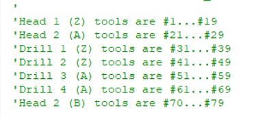
If your machine has an air drill or second spindle, you can use this picture to select the correct bit number. Also make sure to run the Tools > ShopBot Setup routine and select that you have a second cutting head. In the routine, you will be prompted to setup the offset between your spindle and air drill as well using the Z-zero plate with a 5/8” hole drilled in it. See the multiple spindle and air drill offset documentation.
Make sure there is not a comma, period, or other special character in the file name. If changing values in the fill in sheet after loading a file, be sure they are not above/below the max range.
Make a note of when the runtime error pops up. The most common fix for this is to delete the .ini file.
If your computer operating system language is not English-US by default, please review the below computer configuration document.
See: International Computer Configuration (PDF)
Delete INI:
1) First, open a folder and (depending on the version of Windows) there will be either “Organize” in the top left of the folder, or “View” in the toolbar.
a. If in Organize, you will see an option for “Folder and search options” open this and go to step 2.
b. If in View, then you will select “Folder Options”.
2) Find the Hidden Files and Folders category and change the value from don’t show, to show hidden files and folders, and hit OK.
3) Delete the .ini, go to C:/Program Data/ShopBot/ShopBot 3 (This is not on XP) and delete the file called “shopbot” that is the configuration settings file. If on XP, it is in C:/Program Files/ShopBot/ShopBot 3. Once deleted, restart the shopbot software.
If this does not work, follow the software uninstall/reinstall procedure on pages 3-5 of this document: Uninstall and Reinstall SB3
If this error appears right when selecting a settings file for the tool, there is a quick work-around.
For Example:
If originally selecting a PRS tool when the error occurs, instead select a different folder. Select the “Settings for Older Shopbots folder” and select any settings file within. If originally selecting an older tool when the error occurs, instead select a different folder. Select the “PRS Shopbots” folder and select any settings file within. The software should load up without error. Go to Utilities->Reset Default Settings to reselect the correct settings file now.
If the runtime error occurs at a point aside from selecting the settings file, then the easiest fix is to start with deleting the .ini file. The .ini file can be found after showing hidden files and folders. Here is the process:
1) Show hidden files and folders. First, open a folder. Depending on the version of Windows, there will appear either “Organize” in the top left of the folder, or “View” in the toolbar.
a. If in Organize, open “Folder and search options” and go to step 2.
b. If in View, select “Folder Options”.
2) Locate the Hidden Files and Folders category and change the value from don’t show, to show hidden files and folders, and hit OK.
3) Delete the .ini – go to C:/Program Data/ShopBot/ShopBot 3 (This is not on XP) and delete the file called “shopbot” that is the configuration settings file. If on XP, it is in C:/Program Files/ShopBot/ShopBot 3. Once deleted, restart the shopbot software.
If this does not work, follow the software uninstall/reinstall procedure on pages 3-5 of this document: Uninstall and Reinstall SB3
There are two primary types of connection on the cable that runs between the control computer and the control box on the tool, USB and Serial. Each combination of connection types will require specific software versions in order to connect correctly.
USB Type A to B:
Most tools built or upgraded after 2008 will have a USB A to USB B connection.
USB to USB connections will require use of ShopBot control software versions 3.8.XX or higher
The connections will look like this:

Older style connections comprised of Serial connections, or a combination of USB and Serial that runs through an adapter. The adapter will have a serial connection that plugs into the board, with a USB cable plugged into the other end which runs back and plugs into the control computer. Here is the IOGEAR Brand Serial adapter that we sold with our tools for many years. The drivers for this adapter are still available. This type of connection will require ShopBot control software version 3.6.XX.

The third connection type will be Serial to Serial connection. Most modern computers do not even have a Serial port on them, so finding a control computer that will support this type of connection can be difficult. Here is an image of a Serial-to-Serial connection to help. This type of connection will use ShopBot control software version 3.4.XX.

I cannot find the cable that goes between the control box and computer.
If you cannot find the cable that connects between the Control computer and the control box on the tool then we will need to open the control box and examine the electronics inside in order to determine which type of connection is used, and which version of ShopBot control software will be needed. If you want to send a picture of the inside of the control box to Support@ShopBotTools.com we can help identify which connection you have and which version of control software you will need.
New Answer
Most ShopBot tools are equipped with proximity switches that trigger at the ends of travel. There is a routine in the ShopBot software that uses these switches to home the tool to your 0, 0 location. This routine is labeled C3, and can be located two different ways. The first is to go to the Cuts dropdown in the Command Console and then select C3>Home X Y Axes Using Prox Switches. The routine will move each axis in the negative direction until it triggers the proximity switch for that axis. Once it has triggered the switch it will back off and position itself in your home location, then zero itself there. The second way to run the C3 homing routine is to click on the shortcut tile within the Red Position Window with the X and Y letters next to arrows.
C3 Shortcut Tile

This routine uses offsets which are programmable via a different routine. The offsets are easy to reprogram should you ever need to change the home position of the tool, and want that home position to be where the C3 goes to when it is run. As an important note this home position is what all Automatic Toolchanger tool locations are based off of, so if you change these offsets then you will need to recalibrate the toolholder locations, if you are using an Automatic Toolchanger.
Here is how to calculate the offsets for the C3 routine.
First, move the tool into position with your keypad, set it to where you want your 0,0 location to be as exact as you can get it. A vee bit or tapered ballnose bit, something with a fine tip, will make it easier to more accurately position the tool for this location.
After it is in your XY zero location, go to Tools->ShopBot Setup [TS], this will step you through some tool setup questions. You want to get to step 3 (which is the XY prox switch setup), this page has a “Click Here to Make it Easy on me” button that you want to press, a new window will open up, click to start the XY zero setup routine.

This will prompt you to move to the 0,0 location with the keypad, just hit ‘No’ at this step as we have already moved to the correct location, then hit ‘Yes’ to zero at this location.
This will run the homing routine and setup your 0,0 location from there on so the next time you run the C3 (XY home) it will end up where you set it up.
Click next through the rest of the steps and then select I’m Done to save your changes.
This problem can usually be fixed by deleting the Spindle Control folder in the registry. To do so:
1) Click the Start button, type “regedit” into the Search window, and hit Enter to open up the registry editor. Click yes when asked “Do you want to allow the following program to make changes to this computer”.
2) Navigate to the folder HKEY_CURRENT_USER\Software\VB and VBA Program Settings\ShopBot\Virtual Tools
3) Delete the folder – Spindle Control by right clicking on it and selecting delete. This folder will be recreated and populated with the correct settings the next time the Spindle RPM Controller is opened.
Record the error message (take a screenshot!) and record what the tool was doing when the error occurred. Try and find as much info on this error using this FAQ and other ShopBot documentation.
Report this info to Tech Support at support@shopbottools.com if error info is not available in this FAQ.
Manually Loading the USB Drivers:
Starting with Version 3.8.8 of the ShopBot control software the Drivers are no longer installed automatically when the software is installed.
As the final step in installing the software a window will open with the option to check a box that will allow the Driver installation instructions to open next. If you uncheck the box then the instructions will not open.
Here is a linked document that walks through manual installation of the drivers, using the same method that is outlined in text below.
Bring up the device manager. For Windows 7 and up go to step a. For XP machines go to step b.
a) Pull up the start menu, type “Device Manager” (without quotes) into the search bar, click on device manager.
b) Access Device Manager by clicking Start->Control Panel->System->Hardware–> Device Manager Click on the menu item Ports to see if ShopBot Controller (COM#) (where # is some number) appears underneath. If so, the ShopBot Drivers are correctly installed. Otherwise, continue below.
Scroll to an item labelled Other Devices or Unrecognized Devices. Click on it and look for ShopBot Controller, usually labeled V204, with a yellow question mark next to it. Double click to open a properties window.
Under device status, it will say “drivers for this device have not been installed”. Click on the Update or Reinstall button at the bottom of the window. When prompted, DO NOT CLICK Install Automatically. Instead, choose Browse to a Specific Location.
Browse to the main C:\ drive by clicking Computer (on the left) and then clicking OS (C:) or Window (C:). Click on the folder labelled Program Files (x86). If using a 32 bit computer, this folder will not exist – in that case click on the plain Program Files folder. Click on the folder ShopBot-> ShopBot3->Drivers.
Select the folder ShopBotControllerV201. Click Okay or Open to select this folder.
Now the driver should install. The drivers should reinstall automatically. It may be necessary to unplug and re-plug in the USB cable from the tool to the computer
This can be accomplished in one of two ways:
1) Type TR into the ShopBot console (the blank box next to the ShopBot CNC logo). Click on RPM to open the fill-in sheet, and make sure that the correct VFD is selected. Start when SB3 starts to 1.
2) Navigate to C:\Program Files (x86)\ShopBot\Virtual Tools. Open this file with a text editor like Notepad or SBEdit. Edit this one line of code:
· VT = Spindle [&R]PM Control, Virtual Tools\Spindle Control\Spindle Control.exe, 0, 0
· Change the last number, which is a zero, to one. It will now look like this:
· VT = Spindle [&R]PM Control, Virtual Tools\Spindle Control\Spindle Control.exe, 0, 1
· Save the file, close and reopen the SB3 software to see the changes take effect.
Most Common Problem: Computer Interference:
PC Setup
The PC setup can be daunting to many users, and you may need an IT professional to help you, but to succeed with the ShopBot and have it work as smoothly as possible, the control computer must be set up accordingly.
If you are in an educational setting you need your IT dept to provide you a standalone workstation that is not managed by group policy or on the network.
For all applications, the PC must be a clean installed standalone workstation. This will wipe/delete all data/files/programs from the computer.
For the workstation setup a clean install is needed, below is our best information on how:
https://www.youtube.com/playlist?list=PLf632tVju0dEzZ5LnKpb98aaY2HkQMJtj
— Computer Requirements – https://youtu.be/HgsEVSRpJqM
Installing Windows with USB Installer – https://youtu.be/eGQc6uvak3Y
Installing Windows with CD – https://youtu.be/BcGihWMHefk
Setting up Control Computer – https://youtu.be/WEVWW93DvbA
Installing the Control and Design Software – https://youtu.be/-Pb5YzfZcUY
1.) Make sure we are not using a port that is 3.0 if earlier than Windows 10. This is usually a blue colored port or labeled with an SS icon or will just say 3.0 or USB 3.0. We do not want to use this. It is not going to be compatible with the controller. USB 3.0 is fine for windows 10
2.) Make sure the usb cable is not over 10ft or extended in any way.
3.) Make sure the usb port is connected directly in the computer and not a hub.
Electrical Interference
Make sure the cabling for the tool is laid straight and flat without loops/coils. Do not put extra cable in the box.
Ensure the power cable for the cutting head is separated from the other cabling by at least a 1″ air gap over the entire course of its run.
Ground tool – usually grounding dust collection system is sufficient. Otherwise, may want to ground table bed (PRT tools only).
GROUNDING DUST COLLECTION
Links on Dust Collection Grounding
http://www.camheads.org/showthread.php?t=3800
Ideally, use a hose that has copper core wire.
Otherwise, coil a wire up into the hose (this is not ideal).
Connect the copper wire to a large metal object or building ground (preferable) at the dust bag end.
Also make sure the metal body of the dust collector is grounded.
DO NOT have any metal connection running between dust collection and tool – this will cause static to be discharged to the tool rather than away from it.
Other Solutions
Load Firmware.
Check Com Speed.
Check if tool is looking at the wrong port.
Check if the driver is actually loaded.
Check if the excess motor cables are looped up inside the control box.
Check to see if the low voltage sensor cables bundled with the motor cables/power cables.
Check if USB-Serial adapter is dead.
Checking Communication Speed
Depending on the version of the software, perform a baseline test on the communication speeds for the tool. If the version is unknown, check the ShopBot software’s Command Console under Help->About.
This only tests the USB/Serial connection, it does not test the PC in any way.
For 3.8.x versions, perform a move command over a distance of 12 inches. Do this through the command console and not the Keypad by typing a command like: MX, 20 (Move->X axis, 20 inches).
After the move command completes, go to Utilities->Diagnostic Information. The last value on the bottom right of that list should be a value called Packet_et. This is a rough check on how long a command takes to communicate with the controller. This should result in a value of ~35 or less.
For 3.6.x and lower, there should be a program in the C:\Program Files (x86)\ShopBot\Diagnostics folder called USB Speed Test. Perform the test and the tester will display a percentage. The percentage should be 75 or greater.
If these tests result in a poor communication speed, replace the cable connecting the PC to the tool.
*Note: On ShopBot Desktops and MAX, the RPM must be manually adjusted.
The Spindle RPM Control window needs to be open in order for the spindle to change speed. If you see this window pop up during the warm-up routine or software start-up, do not close it. To open it manually, type TR in the ShopBot console (the blank box next to the ShopBot CNC logo). Click on RPM to open the fill-in sheet, and make sure that the correct VFD is selected. Start when SB3 start is set to 1, and the Hz scale is set to 60 for a V1000 spindle and to 100 for a 74X spindle.
The RPM Control window is not available on software versions earlier than 3.6.X.
For the most comprehensive information on PC settings, see the Windows Notes document, or see the notes towards the end of this guide. We strongly advise our pre-setup and tested control computer.
Because ShopBot continuously streams information between the PC and the Control Box, Windows Operating System and other distractions are able to disrupt the smooth motion and operation of the tool and can cause communications problems.
Screen Savers: Disable
Power Save functions: Set these settings to “none” – otherwise, it may cause the computer to slow down in the middle of a cut. LAPTOPS: Powersave mode and will reduce power to the CPU, USB and serial ports, disrupting the connection to ShopBot. Only run ShopBot with plugged in laptop or disable these functions.
Windows Automatic Update: Turn Off. Windows can spend a lot of time checking and downloading the most recent Windows stuff from the web, which can disrupt the cutting file.
Antivirus software: Disable, or set up to check for updates only when first connected to the web.
Other Resource Consuming Software: Resource-consuming software should not be running while the ShopBot control software is open, but there is a lot of software that may be running that is not obvious. This would include any kind of program that occasionally goes to the web and checks for an update. It would also include any active mail monitoring or messaging software.
To be completely sure, disconnect or disable the internet connection while running the ShopBot software. Just closing the browser window does not disconnect the computer from the internet.
PC Setup
The PC setup can be daunting to many users, and you may need an IT professional to help you, but to succeed with the ShopBot and have it work as smoothly as possible, the control computer must be set up accordingly.
If you are in an educational setting you need your IT dept to provide you a standalone workstation that is not managed by group policy or on the network.
For all applications, the PC must be a clean installed standalone workstation. This will wipe/delete all data/files/programs from the computer.
For the workstation setup a clean install is needed, below is our best information on how:
https://www.youtube.com/playlist?list=PLf632tVju0dEzZ5LnKpb98aaY2HkQMJtj
— Computer Requirements – https://youtu.be/HgsEVSRpJqM
Installing Windows with USB Installer – https://youtu.be/eGQc6uvak3Y
Installing Windows with CD – https://youtu.be/BcGihWMHefk
Setting up Control Computer – https://youtu.be/WEVWW93DvbA
Installing the Control and Design Software – https://youtu.be/-Pb5YzfZcUY
1.) Make sure we are not using a port that is 3.0 if earlier than Windows 10. This is usually a blue colored port or labeled with an SS icon or will just say 3.0 or USB 3.0. We do not want to use this. It is not going to be compatible with the controller. USB 3.0 is fine for windows 10
2.) Make sure the usb cable is not over 10ft or extended in any way.
3.) Make sure the usb port is connected directly in the computer and not a hub.
Listed with the software on the Current Software page. Be aware of the type of connection (USB, USB-Serial, and Serial) and the type of controller card used. Contact support with a picture of the controller card if this info is not found.